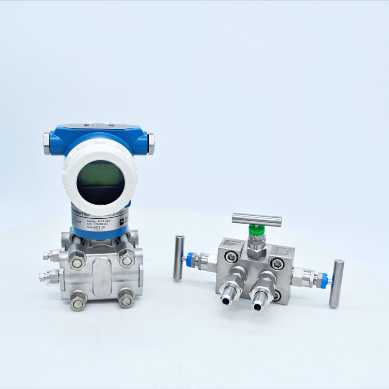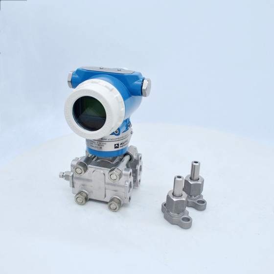
Differential Pressure Transmitter With Manifold Valve
- Information
- Product Description
- Video
- Download
Introduction
The differential Pressure Transmitter is used to prevent the medium in the pipeline from directly entering the transmitter, and the pressure-sensitive diaphragm and the transmitter are connected by a capillary filled with fluid.
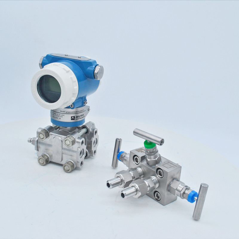
The Differential Pressure Transmitter with manifold valve is a transmitter that measures the pressure difference between the two ends of the transmitter, and outputs standard signals (such as 4~20mA, hart). Differential pressure transmitters are different from general pressure transmitters in that they have 2 pressure interfaces. Differential pressure transmitters are generally divided into positive pressure ends and negative pressure ends. Under normal circumstances, differential pressure transmitters have positive pressure The pressure at the end should be greater than the pressure in the negative pressure section to measure.
The three-valve group is used together with the differential transmitter, and its function is to connect or disconnect the positive and negative pressure measurement chambers with the pressure point; or to disconnect or conduct the positive and negative pressure measurement chambers. It is necessary to use a balancing valve during installation and removal. Otherwise, the range of differential pressure is generally small, and if the overload capacity of the manufacturer is not strong, it is easy to damage.
● High precision
● Span and zero point are continuously adjustable externally
● Good stability
● Adjustable damping and overvoltage resistance
● Diaphragm material in contact with medium is optional
● Unilateral overpressure resistance
●Super measurement performance for pressure, differential pressure, liquid level, flow measurement
●Standard 4-20mA, with digital signal based on HART protocol, remote control
● Supports upgrades to fieldbus and field control-based technologies.
Item | Code | Specification |
| AT3051DP | Differential Pressure Transmitter with manifold valve | |
| AT3051GP | Gauge Pressure Transmitter | |
| Measurement Range | 2 | 0-0.1~1.5 Kpa |
| 3 | 0~7.5 Kpa | |
| 4 | 0~37.4 Kpa | |
| 5 | 0~186.8 Kpa | |
| 6 | 0~690 Kpa | |
| 7 | 0~2068 Kpa | |
| 8 | 0~6890 Kpa | |
| 9 | 0~20680 Kpa | |
| Output | S | 4-20mA, HART Protocol, Linear output |
| J | 4-20mA, HART Protocol, Square root output(Range≥5kpa) | |
| Diaphragm Material / Fill Fluid | 2 | SS 316L Silicone Oil |
| 3 | HC(range >3Kpa) Silicone Oil | |
| A | Stainless Steel 316L Fluorine oil | |
| Drain hole | B | Back of process flange or none |
| U | Process flange side upper | |
| L | Process flange side lower | |
| Wetted O-ring Material | 7 | Buna-N (NBR) |
| 6 | Viton (FKM) (Temperature ≥-20℃) | |
| 5 | Low Temperature Viton (FKM-GFLT) | |
| Process Connection | H | 1/4'' NPT F |
| Maximum Pressure Limit | 1 | 14 Mpa( 4Mpa for range 2) |
| 3 | 25 Mpa | |
| 5 | 32 Mpa | |
| Cable Entry | 1 | M20*1.5 or 1/2'' NPT |
| Mounting Bracket | B00 | None |
| B01 | Tube-type Curved Bracket (carbon steel) | |
| B02 | Wall mounting bracket (carbon steel) | |
| B03 | Tube-type Flat Bracket (carbon steel) | |
| B04 | Tube-type Curved Bracket (stainless steel) | |
| B05 | Wall mounting bracket (stainless steel) | |
| B06 | Tube-type Flat Bracket (stainless steel) | |
| Optional | d | Intrinsically safe type, Flameproof (Exd IIC T4~T6) |
| i | Intrinsically safe (Exia IIC T4~T6) | |
| M3 | LCD display | |
| D1 | Stainless steel drain valve or screw (2pcs) | |
| C1 | 1/2'' NPT female waist flange (2sets) | |
| C12 | 1/2'' NPT-M20*1.5-Φ14 pressure pipe (2sets) | |
| C2 | M20*1.5 male thread T joint (2sets) | |
| C21 | M20*1.5 T joint -Φ14 pressure pipe (2sets) | |
| K1 | Degreasing treatment | |
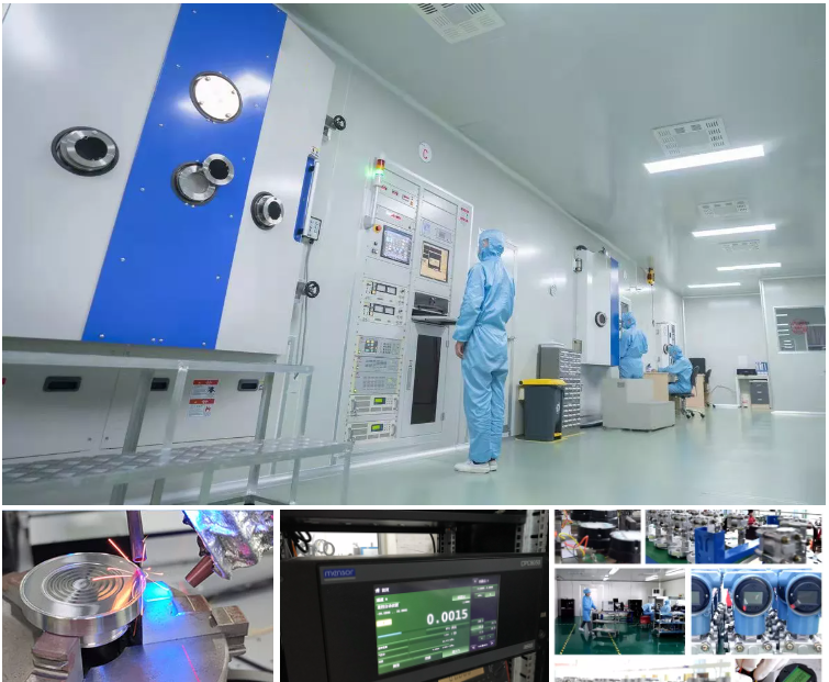
Production Line
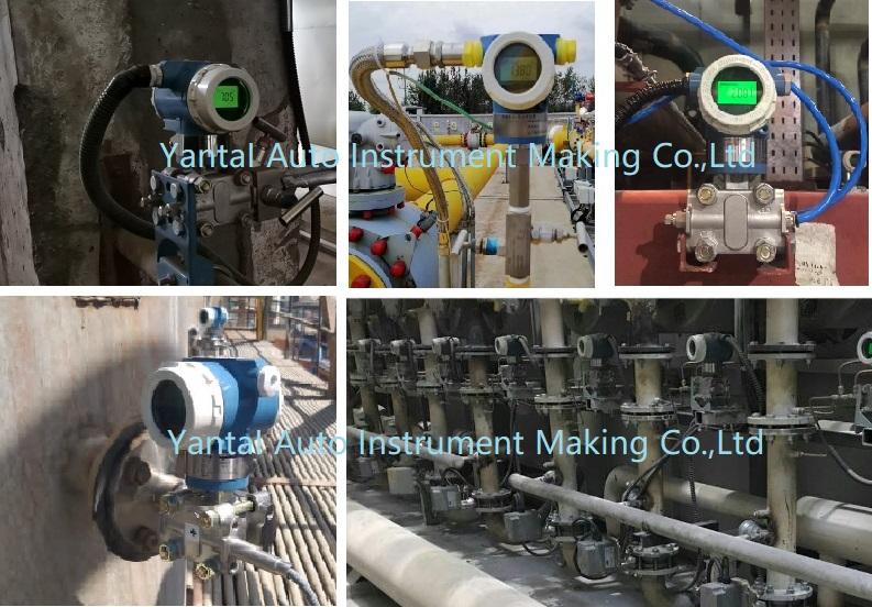
Applications
●Viscous medium at high temperature
●Easy to crystallize medium
●Settling media with solid particles or suspended solids
●Strongly corrosive or highly toxic media
2. The pressures are directly applied to the isolating diaphragm that provide isolation and resistance against process fluid corrosion.
3. Transmitter performance is improved by continuous monitoring of the sensor temperature and corresponding corrections.
4. A local display permits easy reading and writing of data.

